


Introduction to Surface Mount Technology (SMT)
Surface Mount Technology (SMT) is a method of assembling electronic circuits where components are mounted directly onto the surface of a printed circuit board (PCB). This technology has revolutionized the electronics manufacturing industry since its introduction in the 1960s. SMT has largely replaced the traditional through-hole technology (THT) due to its numerous advantages, such as smaller component sizes, higher component density, and improved performance.
Advantages of Surface Mount Technology
- Miniaturization: SMT allows for smaller components and higher component density on PCBs, enabling the production of more compact and lightweight electronic devices.
- Faster assembly: SMT components can be placed and soldered onto PCBs more quickly and efficiently compared to THT components, resulting in faster production times.
- Cost-effective: The automated nature of SMT Assembly and the reduced material costs associated with smaller components make SMT a cost-effective solution for large-scale production.
- Improved performance: SMT components have shorter lead lengths, which reduces parasitic capacitance and inductance, resulting in improved high-frequency performance and signal integrity.
Surface Mount Components
Surface mount components, also known as surface mount devices (SMDs), are designed specifically for use in SMT assembly. These components are typically smaller than their THT counterparts and have leads or terminations that are compatible with surface mounting.
Common Surface Mount Component Packages
- Chip components: Resistors, capacitors, and inductors in small, rectangular packages (e.g., 0201, 0402, 0603, 0805, 1206).
- Small Outline Integrated Circuit (SOIC): A common IC package with gull-wing leads on two sides of the component body.
- Quad Flat Pack (QFP): An IC package with leads on all four sides of the component body, available in various sizes and lead counts.
- Ball Grid Array (BGA): An IC package with an array of solder balls on the bottom surface for connection to the PCB.
| Package | Description | Pitch (mm) | Size (mm) |
|---|---|---|---|
| 0201 | Chip component | 0.25 | 0.6 x 0.3 |
| 0402 | Chip component | 0.5 | 1.0 x 0.5 |
| 0603 | Chip component | 0.8 | 1.6 x 0.8 |
| 0805 | Chip component | 1.25 | 2.0 x 1.25 |
| 1206 | Chip component | 1.6 | 3.2 x 1.6 |
| SOIC | IC package | 1.27 | varies |
| QFP | IC package | varies | varies |
| BGA | IC package | varies | varies |

Surface Mount Technology Assembly Process
The SMT assembly process consists of several key steps that ensure the proper placement and soldering of components onto the PCB.
Solder Paste Application
Solder paste, a mixture of tiny solder particles and flux, is applied to the PCB’s surface using a stencil or screen printing process. The stencil has openings that correspond to the component pads on the PCB, allowing the solder paste to be deposited precisely where needed.
Component Placement
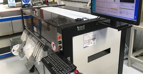
Surface mount components are placed onto the solder paste-coated pads using automated pick-and-place machines. These machines use computer-controlled nozzles or grippers to pick up components from feeders and place them accurately on the PCB at high speeds.
Reflow Soldering
After component placement, the PCB undergoes a reflow soldering process. The assembly is heated in a reflow oven, which follows a specific temperature profile to melt the solder particles in the paste, forming a strong electrical and mechanical connection between the components and the PCB. The temperature profile typically includes:
- Preheat: Gradually raising the temperature to activate the flux and remove any moisture.
- Soak: Maintaining a steady temperature to ensure even heating of the assembly.
- Reflow: Rapidly increasing the temperature to melt the solder particles and form the solder joints.
- Cooling: Gradually lowering the temperature to allow the solder joints to solidify.
Inspection and Testing
After the reflow soldering process, the assembled PCBs undergo visual inspection and automated optical inspection (AOI) to detect any defects or misaligned components. Electrical testing, such as in-circuit testing (ICT) or functional testing, may also be performed to ensure the proper operation of the assembLED Circuit.

Design Considerations for Surface Mount Technology
When designing PCBs for SMT assembly, several factors must be considered to ensure manufacturability, reliability, and optimal performance.
Component Selection
Choosing the appropriate surface mount components for the design is crucial. Factors to consider include:
- Package size: Select components with package sizes that are compatible with the available PCB space and the assembly process capabilities.
- Electrical specifications: Ensure that the chosen components meet the required electrical specifications, such as voltage rating, tolerance, and power dissipation.
- Availability: Consider component availability and lead times to avoid potential supply chain issues.
PCB Layout
Proper PCB layout is essential for successful SMT assembly. Key considerations include:
- Pad size and spacing: Design component pads with appropriate sizes and spacing to accommodate the selected component packages and ensure reliable solder joint formation.
- Trace width and spacing: Ensure that PCB Traces have sufficient width to carry the required current and are spaced appropriately to minimize crosstalk and signal integrity issues.
- Thermal management: Provide adequate thermal relief for components that generate significant heat, using techniques such as copper pours, Thermal Vias, or heat sinks.
Assembly Process Compatibility
Design the PCB and select components with the SMT assembly process in mind. Consider factors such as:
- Stencil design: Ensure that the solder paste stencil apertures are appropriately sized and shaped for the component pads to achieve proper solder paste deposition.
- Pick-and-place machine capabilities: Select component packages and placement locations that are compatible with the capabilities of the available pick-and-place machines.
- Reflow profile: Design the PCB and select components that are compatible with the reflow soldering temperature profile to avoid component damage or poor solder joint formation.

Advantages of Surface Mount Technology over Through-Hole Technology
Surface Mount Technology offers several advantages over traditional Through-Hole Technology (THT):
- Space savings: SMT components are smaller and can be placed on both sides of the PCB, resulting in higher component density and more compact designs.
- Weight reduction: SMT assemblies are generally lighter than THT assemblies due to the smaller component sizes and the absence of leads that extend through the PCB.
- Improved high-frequency performance: SMT components have shorter lead lengths, which reduces parasitic effects and improves signal integrity at high frequencies.
- Faster assembly: SMT assembly is highly automated, allowing for faster placement and soldering of components compared to manual THT assembly.
- Lower production costs: The automation and reduced material usage in SMT assembly lead to lower overall production costs, especially for high-volume manufacturing.
Challenges and Limitations of Surface Mount Technology
Despite its many advantages, SMT also presents some challenges and limitations:
- Component handling: SMT components are small and delicate, requiring specialized handling equipment and processes to avoid damage during assembly.
- Rework and repair: Reworking or repairing SMT assemblies can be more challenging compared to THT assemblies due to the smaller component sizes and the need for specialized tools and techniques.
- Thermal management: The high component density in SMT assemblies can lead to increased heat generation, requiring careful thermal management to ensure reliable operation.
- Inspection and testing: Inspecting and testing SMT assemblies can be more complex due to the smaller component sizes and the presence of components on both sides of the PCB.
Future Trends in Surface Mount Technology
As the electronics industry continues to evolve, SMT is also adapting to meet new challenges and demands:
- Miniaturization: The trend towards smaller, more compact electronic devices is driving the development of even smaller SMT component packages, such as 01005 chip components and wafer-level packaging (WLP).
- Advanced packaging technologies: Emerging packaging technologies, such as package-on-package (PoP) and 3D integrated circuits (3D-ICs), are being used in conjunction with SMT to create high-density, high-performance assemblies.
- Flexible and stretchable electronics: SMT is being adapted for use in flexible and stretchable electronic applications, such as wearable devices and medical implants, through the use of flexible PCB materials and specialized assembly techniques.
- Increased automation: Advances in automation technologies, such as robotic assembly systems and machine vision, are further improving the speed, accuracy, and reliability of SMT assembly processes.
Frequently Asked Questions (FAQ)
- What is the difference between Surface Mount Technology (SMT) and Through-Hole Technology (THT)?
- SMT involves mounting components directly onto the surface of a PCB, while THT involves inserting component leads through holes in the PCB and soldering them on the opposite side. SMT components are smaller, allow for higher component density, and enable faster assembly compared to THT components.
- Can SMT and THT components be used together on the same PCB?
- Yes, it is possible to use both SMT and THT components on the same PCB in a mixed-technology assembly. However, this may require additional design considerations and assembly steps to accommodate both types of components.
- What is solder paste, and how is it applied in SMT assembly?
- Solder paste is a mixture of tiny solder particles and flux that is used to form the electrical and mechanical connections between SMT components and the PCB. It is typically applied to the component pads on the PCB using a stencil or screen printing process prior to component placement.
- What is a reflow oven, and how does it work in SMT assembly?
- A reflow oven is a specialized oven used in SMT assembly to melt the solder paste and form the solder joints between components and the PCB. The oven follows a specific temperature profile, heating the assembly to activate the flux, melt the solder particles, and then cooling it to allow the solder joints to solidify.
- What are some common challenges faced when designing PCBs for SMT assembly?
- Some common challenges in designing PCBs for SMT assembly include selecting appropriate component packages, designing proper pad sizes and spacing, ensuring adequate thermal management, and ensuring compatibility with the SMT assembly process capabilities, such as stencil design and pick-and-place machine limitations.
Conclusion
Surface Mount Technology has revolutionized the electronics manufacturing industry, enabling the production of smaller, lighter, and higher-performance electronic devices. By understanding the fundamentals of SMT, including component packages, assembly processes, and design considerations, engineers and manufacturers can effectively leverage this technology to create innovative and reliable electronic products. As the electronics industry continues to evolve, SMT will play a crucial role in shaping the future of electronic packaging and assembly.