

Introduction to PCBs
A printed circuit board (PCB) is a board made of insulating material like fiberglass, composite epoxy, or other laminate materials, used to mechanically support and electrically connect electronic components using conductive pathways or traces. PCBs provide the necessary foundation for circuit designs and allow components to be interconnected in a compact format.
PCBs can be broadly classified into two categories – rigid and flexible. Both have their own set of advantages and applications. This article provides an in-depth comparison between rigid and flexible PCBs.
Rigid PCBs
What are Rigid PCBs?
A rigid PCB is the most common type of PCB. As the name suggests, these boards retain their shape and do not bend or flex. Rigid PCBs consist of a solid laminate base material like FR-4 glass epoxy. The circuit is etched or printed on the board and then components are soldered on.
Properties and Composition
- Made of rigid insulating materials like FR-4 glass epoxy
- Retains its shape – does not flex or bend
- Provides structural stability
- Multiple layers of copper conductors laminated with prepreg bonding material
- More than 85% glass fiber content provides rigidity
- Highly suited for complex, high density designs
Applications and Use Cases
Rigid PCBs are ideal for –
- Consumer electronics – Mobile phones, computers, gaming consoles etc
- Industrial electronics and machinery
- Medical equipment
- Automotive electronics
- Aerospace and defense equipment
- Communication infrastructure
Any application requiring miniaturized, complex and dense circuitry with need for structural stability is well suited for rigid PCBs. The rigidity provides protection against shock, vibration and mechanical stress.
Advantages of Rigid PCBs
- Structurally rigid and stable
- Multiple layers possible for complex circuitry
- Miniaturized design with components mounted on both sides
- Excellent thermal performance
- Good electrical insulation
- Cost effective for medium to high volume production
- Supports automated assembly
- Long product life span
Limitations of Rigid PCBs
- Requires careful handling as rigid boards can crack
- Modifications and repairs difficult after production
- Limited flexibility in product design
- Size and shape restrictions
Rigid PCBs serve most common electronics applications but their rigidity makes them unsuitable for flexible or moving products.
Flexible PCBs
What are Flexible PCBs?
As the name indicates, flexible PCBs can bend and flex while still retaining their electrical functionality. They are made of flexible insulating materials which allow them to be folded or wrapped around surfaces. Flex PCBs provide excellent mechanical versatility for products that need to move, twist or conform to space constraints.
Properties and Composition
- Made of thin, flexible insulating material like polyimide
- Can conform to any shape or be folded
- Robust enough to withstand repeated bending
- Uses thin flexible copper laminates for traces
- Fiberglass-free construction provides flexibility
- Lightweight and thin
- Single or double layered circuitry
Applications and Use Cases
Flexible PCBs are used when –
- Product needs to flex or change shape dynamically
- Design has complex or moving parts
- Size and space constraints require folded/bent PCBs
- Weight minimization is critical
- Durability under mechanical stress is needed
Common applications include –
- Wearable technology – smart watches, health trackers
- Medical devices
- Consumer electronics – smartphones, displays
- Robotics and UAVs
- Vehicles – sensors and control modules
- IoT edge devices
- Flexible displays and signage
Any product with flexing, moving or changing form factors can utilize flexible PCBs. The ability to bend and fold allows fitting circuitry in tight spaces.
Advantages of Flex PCBs
- Can conform to any shape or moving part
- Withstands vibration, shock and stress
- Lightweight and takes up less space
- Allows for compact, thin product designs
- Simplifies assembly of complex shapes
- Allows movement and portability
- Rapid prototyping ability
- Single sided flex circuits cost effective
Limitations of Flex PCBs
- Limited in terms of circuit complexity
- Heating and cooling management issues
- Prone to cracking on folds if not properly designed
- Not suited for high voltage, high frequency circuits
- More expensive for small volume or prototype builds
While flexible PCBs provide unmatched mechanical versatility, they lack the complexity, miniaturization and thermal performance of rigid PCBs.
Comparing Rigid vs Flexible PCBs
Below table summarizes the key differences between the two types of PCBs:
| Parameter | Rigid PCB | Flexible PCB |
|---|---|---|
| Composition | FR-4, other rigid laminates | Polyimide, liquid crystal polymer |
| Construction | Multiple layers | Usually single or double layer |
| Circuit Density | Very high | Low to moderate |
| Thermal Performance | Excellent | Poor heat dissipation |
| Complexity | Support complex, dense designs | Suitable for simpler circuits |
| Shape | Flat, fixed shape | Can be bent, folded or twisted |
| Mechanical Strength | Very strong | Susceptible to cracks on folding |
| Cost | Lower cost for volume production | Higher cost for short runs |
| Applications | Consumer electronics, computers, machinery | Wearables, medical devices, flexing electronics |
When to use Rigid PCBs
Rigid PCBs should be chosen when –
- High component density is required
- Electrical performance is critical (high speed, high frequency, low noise)
- Excellent thermal performance is needed
- Structural stability and strength are important
- Lower costs is key driver for volume production
- Automated assembly will be used
- Product life cycles are long
When to use Flexible PCBs
Flexible PCBs provide the best choice when –
- Product needs to change shape or move dynamically
- Compact, thin circuitry is required
- Ability to withstand vibration, shock, stress is critical
- Weight and space constraints exist
- Product has complex bends or folds
- Faster prototyping is beneficial
- Medium volume production
By considering the application requirements, constraints, product life cycle and target environment, engineers can determine the optimal PCB technology – rigid or flex. Many products may use a combination of both rigid and flex PCBs to leverage their complementary strengths.
PCB Assembly and Component Mounting
Once designed and fabricated, PCBs need to be assembled and components mounted. There are some key differences in assembly of rigid vs. flex PCBs:
Rigid PCB Assembly
- Automated assembly using surface mount and through-hole technologies
- For dense double sided mounting, automated soldering is preferred
- Multiple components can be placed programmatically
- Automated optical inspection (AOI) checks quality
- Economical for medium to high volume
Flexible PCB Assembly
- Manual placement of components
- Reflow soldering done in oven after alignment
- Addition of stiffener plates provide stability
- Lower volume production – more manual labor
- AOI systems need to account for flexing
Future Trends
Rigid PCBs
- Techniques to dissipate heat effectively from high density electronics
- Built-in antennas, filters and shielding
- Higher number of layers and densities
- Split planes and buried/blind vias for densification
- Improved materials like ceramic-filled substrates
Flexible PCBs
- New materials like liquid crystal polymer for increased flexibility
- Better thermal management
- Embedded passives and actives
- Flex-to-rigid PCB assemblies
- Flexible circuits with stretchability and elasticity
- Innovation in flex PCB based products like wearables and IoT
Both rigid and flexible PCBs will continue to evolve with design and material innovations. The growth of electronics in new form factors will drive new demand for flex PCBs. However, rigid PCBs will continue to dominate high reliability electronics due to their structural stability and reliability. Engineers need to make informed design choices based on application requirements.
Frequently Asked Questions on Rigid vs Flexible PCBs
Q1. Why are rigid PCBs more common than flexible PCBs?
Rigid PCBs are more prevalent because they can support complex, dense circuitry which is needed in most electronics like computers and consumer devices. Their stability also makes them suitable for products having long product lifecycles. The lower cost of rigid PCBs at scale also improves adoption.
However, flexible PCB usage is increasing rapidly with new applications in wearable and flexible electronics.
Q2. Can flexible PCBs offer the same level of miniaturization as rigid PCBs?
Flexible PCBs are limited to 1 or 2 conductive layers which restricts the level of miniaturization achievable versus multi-layer rigid boards. Rigid PCBs support high density interconnections on multiple layers enabling greater miniaturization.
Q3. Do flexible PCBs fail faster than rigid PCBs?
With proper design, flexible PCBs can have comparable reliability. Failures can occur if not properly designed for the required bending cycles. Stress relief techniques need to be incorporated at bending points. RG178 coaxial cables handle flexing well for high frequency signals.
Q4. How are components mounted on flexible PCBs?
There are three main techniques:
- SMT components can be soldered directly for single-sided flex PCBs
- Through-hole components attached with adhesive first, then soldered
- Connectors and ICs use SMT, soldered to stiffener plates first to maintain stability during soldering
Automated assembly is challenging, so manual assembly is common for low/mid-volume flexible PCB production.
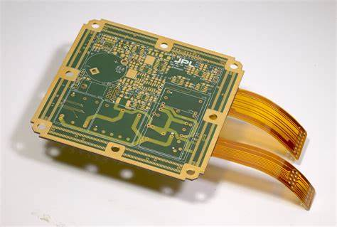
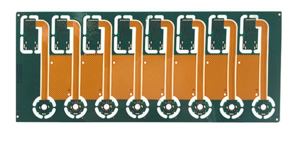
Q5. Can a single product use both rigid and flexible PCBs together?
Yes, many products couple the strengths of both PCB types. A common technique is to have rigid PCBs for the main processing circuitry, joined using flex PCBs that interconnect and route signals between the rigid PCBs. This allows flexibility needed in certain areas while utilizing rigid PCBs for complex circuits.
Conclusion
Rigid and flexible PCBs offer complementary strengths serving different applications. Rigid PCBs support complex, dense circuitry and excel in products requiring structural stability and long lifecycles. Flexible PCBs provide mechanical versatility for dynamic shape changing products, albeit with simpler circuitry.
Engineers need to balance these trade-offs during design to map the right PCB technology to product requirements. With both rigid and flex PCB technologies advancing, they will continue improving electronics across diverse applications.