


Rigid flex PCBs combine rigid boards and flexible circuits into a single integrated assembly. They provide design flexibility and can improve reliability and space savings in electronic devices. For many products, especially those incorporating wearable technology or needing to fit into tight spaces, rigid flex may be the optimal PCB design choice.
When you need functional rigid flex prototypes or low volume production quickly, relying on a quick turn PCB manufacturer is key. With an experienced quick turn partner, you can have high quality rigid flex PCBs in hand in just days or weeks, not months.
This guide covers key considerations in specifying and ordering quick turn rigid flex PCBs to help you get the most cost-effective boards in the shortest time.
What Are Rigid Flex PCBs?
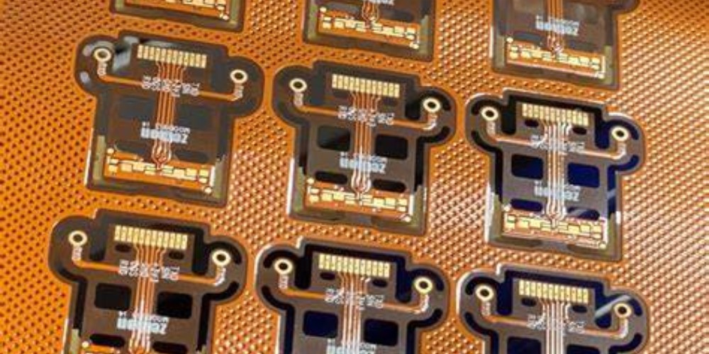
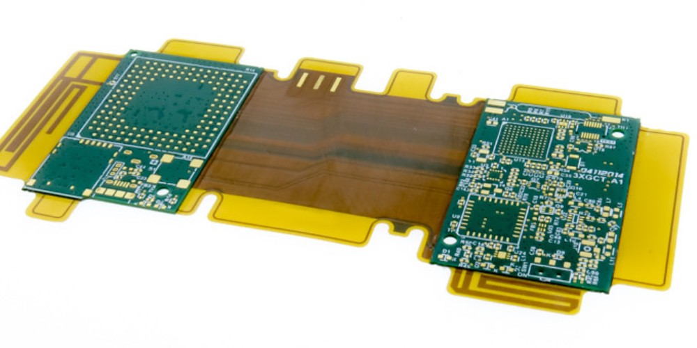
A rigid flex PCB combines stiff printed circuit board materials with thin, flexible circuits linking multiple rigid areas together. They facilitate 3-dimensional configuration and dynamic flexing to accommodate movement, vibration, or irregular component placement.
Rigid flex PCBs have three primary components:
- Rigid sections – Made from typical PCB materials like FR-4. Provide structure and component mounting.
- Flexible sections – Thin polyimide film layers with etched copper traces. Allow dynamic movement and shaping.
- Bonded sections – Where rigid and flex layers are joined with adhesive.
By integrating both rigid and flexible materials into a single assembly, rigid flex PCBs provide:
- Ability to fold and shape PCBs to fit products
- Reliable flexing and motion capacity
- Component mounting on multiple rigid areas
- Layer stacking for high density interconnections
- Efficient cabling replacement with flex jumpers
- Reduced system wiring and connectors
- Lighter, more compact product design
Typical applications that benefit from rigid flex PCBs:
- Wearable devices
- Internet of Things (IoT) products
- Medical equipment
- Automotive electronics
- Aerospace and defense systems
- Consumer electronics
For products where size, weight, reliability, and high interconnect density matter, rigid flex offers key advantages over traditional FR-4 boards or wired cabling between PCBs.
Why Use Quick Turn Rigid Flex PCBs
For prototyping or short run production, relying on a quick turn PCB manufacturer to produce your rigid flex boards can save you time and money versus traditional long lead vendors.
Benefits of quick turn rigid flex include:
Faster time to market – Quick turn assembly in as little as 24-48 hours for bare bones ” rally boards” and 5-10 days for complete populated assemblies.
Lower costs – No need for large volume orders to get good pricing. Ideal for prototyping through low volume production up to a few thousand boards.
High quality – Experienced manufacturers use latest fabrication equipment and processes to deliver consistent, high-reliability PCBs.
Design for manufacturing (DFM) expertise – Get guidance to avoid manufacturability issues and optimize rigid flex design.
Flexible ordering – Order exactly what you need from bare PCBs to complete turnkey assemblies. Modify and iterate faster.
Rapid delivery – Avoid long lead times. Get populated boards in days/weeks rather than months.
Superior support – Get hands-on help from engineering experts over phone, email, and chat.
For innovators working on cutting edge rigid flex products on a budget, quick turn fabrication can make the difference in being first to market at low cost.
Key Specifications for Quick Turn Rigid Flex PCBs
To get quality quick turn rigid flex PCBs delivered fast, you need to provide key specifications and requirements to your manufacturer. Here are common parameters to define:
Layer Count
How many conductive layers are required? Rigid sections commonly use 2 to 30+ layers. Flexible sections often use 1-2 layers. More layers allow higher component density but increase complexity and cost.
Board Thickness
Total thickness including all rigid, flex, and bonded sections. Rigid areas typically 0.4mm to 5mm. Flex areas around 0.05mm to 0.25mm. Thicker boards provide stability but limit bend radius.
Board Size
Dimensions of the overall board and any internal cutouts. Consider manufacturer’s maximum panel size. Smaller boards cost more per area than larger boards.
Rigid vs. Flex Areas
Define the size and location of all rigid and flex sections required. Provide mechanical drawings showing desired 3D configuration.
Materials
Rigid sections typically use standard FR-4 material. Flexible sections use polyimide films like Kapton. Specify dielectric materials, copper weights, and glass fiber reinforcements.
Finishes and Coatings
Solder mask, silkscreen, immersion gold, ENIG, and other finishes. Flex areas often use coverlay and stiffeners for protection and support. Specify requirements.
Bonded Sections
Adhesive between rigid and flex layers. Thermal bonding with pressed layers or glued sections. Specify type of bonding desired.
Density and Tolerances
Line width/space, via sizes, registration accuracy needed. Rigid areas can achieve finer features than flex circuits.
Testing
Electrical testing, inspection, and any other verification required. Rigid-flex testing can be complex.
DFM Guidelines
Specify DFM and assembly requirements. Provide suggestions to avoid manufacturability issues.
Use rigid-flex design principles and communicate closely with your PCB manufacturer early in the design process. This ensures your design is optimized for quick turn manufacturing.
How Rigid Flex PCB Manufacturing Works
Fabricating quality rigid flex PCBs requires specialized processes and equipment. Here is a general overview of manufacturing steps:
Design and Documentation
A customer provides board requirements, Gerber files, mechanical drawings, assembly notes, and other specifications to define the rigid flex product.
CAM Processing
The PCB manufacturer analyzes the design data, adds fabrication details, and converts all information into manufacturing machine instructions.
Material Selection
Compatible rigid and flex materials are chosen per specifications. This includes dielectric layers, copper foils, cover layers, bonding films, and other components.
Imaging
Rigid layers are fabricated as standard PCBs with imaging and etching to define circuit patterns on multiple layers aligned with precision.
Lamination
Rigid layers are pressed together with bonding sheet layers in between. Temperature and pressure bind the layers into a unified board.
Flex Patterning
Flex layers are produced by selectively etching metal foils bonded to thin polyimide films. The resulting circuit patterns are precision aligned.
Layer Assembly
Finished rigid sections and flex layers are carefully aligned and bonded together with adhesive films or thermal bonding techniques.
Component Assembly
For populated boards, surface mount and through hole components are selectively placed and soldered. Often done by automated assembly lines.
Testing and QA
100% electrical testing validates connectivity. Automated optical inspection and human review verify quality and assembly precision. Failed boards are reworked or replaced.
Scoring and Shipping
Finished boards are routed, scored, and depanelized from production panels. Final QC check before shipping to customer.
By working with an experienced, well-equipped manufacturer, you can get high quality rigid flex PCBs produced rapidly even in low volumes suitable for prototyping.
Design for Manufacturing Guidelines
Following design for manufacturing (DFM) principles when designing your rigid flex PCB will help ensure a cost-effective, manufacturable design. Key guidelines include:
- Minimize rigid-to-flex transitions – Each transition adds cost. Design with fewer rigid areas when possible, separating them with long flex sections.
- Avoid small rigid sections – Rigid areas less than 2″ x 2″ are difficult to handle without breakage. Build more margin into small sections.
- Balance layer counts – Adding layers in only rigid or flex areas can cause bonding problems. Keep layer counts similar in both sections.
- Watch rigid/flex thickness differences – Thickness deltas over 2:1 can lead to stresses. Use similar thicknesses where possible.
- Limit unsupported span length – Long flexible sections will droop without support. Add stiffness with covers or bonding to carriers if needed.
- Design panels efficiently – Position boards to maximize panel utilization. Leave room for tooling and dam bars between boards.
- Facilitate lamination – Thermal balancing, even copper distribution, and release paths help material flow in lamination.
- Watch trace densities – Avoid necks or shadows. Use larger features on outer layers if possible.
By adhering to DFM principles and seeking manufacturer input, you can optimize the design for reliability, manufacturability, and rapid production.
Examples of Quick Turn Rigid Flex Applications
Here are a few examples of products using quick turn rigid flex PCBs during development and early manufacturing.
Wearable Health Monitor
This small health monitoring device required a compact, highly flexible PCB design. A 4-layer rigid flex allowed all components to mount on a small 0.8mm thick rigid section. Thin polyimide flex layers connect to the biosensors that wrap around the wearer’s limb.
Drone Flight Controller
Folding rigid flex PCBs with polyimide flex joints were used to create durable navigation controllers for quadcopter drones. The rigid sections provide stability for the SMT components while the flex layers withstand repeated motion and vibration.
Laptop Hinge Interconnect
Opening and closing a laptop lid thousands of times can break solder joints. This manufacturer used a multilayer rigid flex to route signals from lid to base. The dynamic flexing avoided mechanical failures.
Medical Pump Control Board
After reliability issues with cabled boards, this designer switched to a rigid flex design. The rigid board hosts the circuitry while the thin flex layers snake through the device to operate the pumping mechanism.
In each case, quick turn rigid flex prototyping proved the design and led to low volume production. The combination of rapid fabrication and engineering support allowed these companies to be first to market without high NRE and tooling costs.
Finding the Best Quick Turn Rigid Flex Partner
Choosing the right PCB manufacturer is key to getting quality quick turn rigid flex boards. Here are top criteria to look for:
- Experience with rigid flex – Seek specialists with case studies, not just claims. Evaluate their expertise.
- In-house capabilities – Look for complete in-house manufacturing without outsourcing. This minimizes delays and errors.
- Tooling and processes – Ensure they have dedicated rigid flex equipment like laser direct imaging (LDI), lamination presses, etc.
- Engineering support – The ability to consult with engineers to refine your design is invaluable.
- Quality certifications – Look for ISO 9001 and other process certifications to ensure consistency.
- Reviews and reputation – Check testimonials, customer reviews, and industry reputation. The best have proven happy customers.
By selecting a top tier rigid flex PCB manufacturer for your quick turn needs, you gain the knowledge and capabilities required to deliver high quality boards rapidly. The results are reduced risk, faster time-to-market, and lower costs.
Quick Turn Rigid Flex PCBs FQA
Here are answers to some frequently asked questions about specifying and ordering quick turn rigid flex PCBs:
How long does it take to get quick turn rigid flex PCBs?
A typical turnaround is 5-10 days for production ready boards. Simple 2-4 layer designs can potentially be fabricated in just 24-48 hours. Populate times vary based on complexity.
What are the minimum order quantities?
Because quick turn shops focus on prototyping and low volume production, minimums are often just 1-2 boards. This allows cost-efficient testing of designs.
What file formats do they need?
Gerber and drilling files are standard inputs. IPC-2581 archive files are also welcomed. Provide layered mechanical drawings in DWG or PDF format.
Can they assemble components and test completed boards?
The best quick turn shops offer full assembly, testing, inspection, and other value-added services. This allows you to receive finished populated PCBs.
How do you make design revisions?
During the prototyping stage, design changes can usually be implemented very rapidly, often within 1-2 days. No new NRE fees when using the same fabrication line.
Can they manufacture in low volumes?
Yes, quick turn production is ideal for volumes from 1 to 1,000 boards. For higher quantities, extended production runs provide cost savings.
How can design for manufacturing help?
DFM analysis by engineers can spot any issues early so the design can be adjusted to avoid problems and ensure a manufacturable board design.
Relying on an experienced quick turn PCB manufacturer specializing in rigid flex technology provides huge advantages for bringing new products to market faster and cheaper. Their expertise and capabilities are key to delivering high quality prototypes and early production boards.