


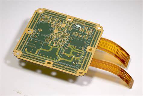
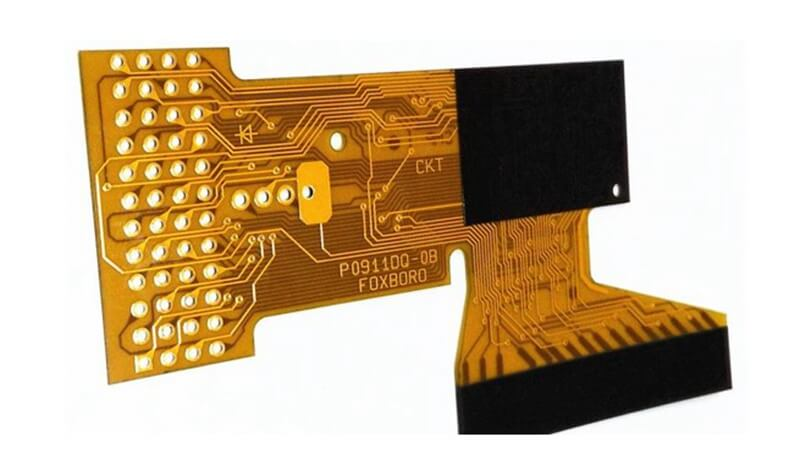
Flexible printed circuits (FPCs) are widely used in modern electronics due to their ability to bend and flex to fit into tight spaces. A key component of FPCs is the coverlay, a thin insulating layer that protects the conductive circuitry. Flex coverlays provide electrical insulation and mechanical protection while maintaining flexibility and allowing connections between layers. This article provides an in-depth look at flex coverlays, their properties, types, and applications.
What is a Flex Coverlay?
A flex coverlay is a thin, flexible dielectric film laminated over the conductor pattern of the flex circuit. It serves to insulate the conductive copper traces from the environment and from shorting out against other conductors or components. The coverlay overlaps the edges of the conductors to prevent migration of environmental contaminants like moisture and dust.
Flex coverlays are made from polyimide, polyester, fluoropolymer, or other flexible polymer films. These materials can be formulated with adhesives on one or both sides to allow lamination over the FPC conductors. Coverlays typically range from 12.5 to 100 microns (0.5 to 4 mils) in thickness.
The primary functions of flex coverlays:
- Electrical insulation between conductors
- Environmental protection from moisture, dust, chemicals
- Mechanical support and abrasion/cut-through resistance
- Solder mask during assembly to prevent bridging between pads
- Dielectric for flexible printed circuits with multiple layers
Key Properties of Flex Coverlays
Flex coverlays must possess a careful balance of electrical, mechanical, chemical, and thermal properties to function effectively in FPC applications. Some key parameters are outlined below:
Dielectric Strength: This refers to the voltage required to electrically break down the insulator material. Typical dielectric strength values range from 300 to 2000 V/mil.
Dielectric Constant: This property affects signal propagation speed and impedance control. Typical values are 3.0 to 3.5 for polyimide and 2.5 to 3.2 for polyester films.
Dissipation Factor: Also called loss tangent, this indicates how much electrical energy is lost in the insulator. Lower values under 0.02 are preferred.
Thermal Stability: Coverlay films must withstand FPC processing temperatures up to 200°C and operation up to 130°C without melting, deforming, or degrading.
Flexibility: Minimum bend radius ranges from 2 to 10X the film thickness. Flexibility ensures conformity and movement with the FPC.
Flammability: Coverlay films are engineered to be self-extinguishing to meet flammability standards like UL-94 VTM-0.
Chemical Resistance: Compatibility with common PWB processing chemicals is required. Polyimide offers the best resistance.
Types of Flex Coverlays
There are two main categories of coverlay materials used in flex circuit fabrication:
Polyimide Coverlays
Polyimide films offer the best thermal, mechanical and chemical properties at a reasonable cost. This makes polyimide the most common type of coverlay for FPCs. Popular polyimide coverlay brands include DuPontTM Kapton®, Ube UPILEX®, and Kaneka Apical®. Polyimide coverlays are available in 12.5 to 100 micron thicknesses.
Polyester Coverlays
Polyester films like PET (Mylar®) are also used as FPC coverlays. Polyester is less expensive than polyimide but has lower maximum use temperatures. Polyester coverlays can be a good choice for low-cost, low-temperature applications. Common thicknesses range from 12.5 to 50 microns.
Other specialty coverlay materials like fluoropolymers (PTFE), LCP, and thermoplastic polyurethane (TPU) are used in specific applications. The table below compares properties of common flex coverlay materials.
| Property | Polyimide | Polyester | Fluoropolymer |
|---|---|---|---|
| Dielectric Strength | 5000-7000 V/mil | 1000-1500 V/mil | 1000 V/mil |
| Dielectric Constant | 3.4-3.6 | 3.0-3.2 | 2.1-2.2 |
| Thermal Stability | Up to 200°C | Up to 125°C | Up to 155°C |
| Chemical Resistance | Excellent | Moderate | Excellent |
| Cost | Moderate | Low | High |
Flex Coverlay Adhesive Options
In order to laminate the coverlay onto the FPC, some form of adhesive is required. There are three main adhesive types used:
- Liquid photoimageable coverlay (PIC) – A B-staged adhesive is applied to the coverlay film which is activated and imaged during lamination. This allows selective bonding in the z-axis.
- Dry film adhesive – The coverlay film comes with a laminated dry film adhesive, typically acrylic or epoxy-based.
- Pressure sensitive adhesive (PSA) – The adhesive is already coated on the coverlay film so lamination can be performed with just heat and pressure.
Each adhesive option has tradeoffs between cost, ease of processing, and performance:
| Coverlay Adhesive System | Benefits | Drawbacks |
|---|---|---|
| Liquid PIC | Excellent chemical resistance, selective bonding | High cost, complex processing |
| Dry film | Moderate cost, ease of processing | Limited chemical resistance |
| PSA | Low cost, easiest processing | Low high temperature resistance |
Coverlay Processing and Lamination
There are several key steps required to properly apply the coverlay film onto the FPC circuitry:
Surface Preparation: The FPC surface must be thoroughly cleaned to ensure good adhesion. Any oils, soils or processing residues will be an impediment.
Alignment: The coverlay must be precisely aligned to the FPC conductors to avoid issues like open circuits. Automated optical alignment systems are typically employed.
Lamination: Heat and pressure are applied to activate the adhesive and bond the coverlay. Typical parameters are 185°C at 200 psi for 60-120 minutes depending on adhesive type.
Curing: A post-lamination curing cycle is often required to fully crosslink the adhesive system. This helps prevent delamination issues.
Via Formation: The coverlay must be patterned with vias (openings) over solder pads. This allows soldering to the pads during assembly. Lasers are commonly used for clean, selective patterning.
Final Finishing: Edge trimming, contouring, hole punching, slitting and other finishing steps prepare the coverlayed FPC for assembly.
Common Coverlay Defects
Care must be taken during coverlay processing and lamination to avoid defects which can lead to flex circuit failures:
- Delamination – Adhesive failure allowing separation of coverlay from FPC. Caused by poor surface prep, mismatched expansion, or weak adhesive.
- Wrinkles/Folds – Uneven coverlay surface from misaligned lamination. Can cause electrical shorts.
- Blisters – Trapped air or moisture creating raised bumps under coverlay. Adhesive voids reduce dielectric strength.
- Cut-through – Coverlay damage from via formation or finishing exposes conductors. Allows short circuits.
- Alignment Issues – Misregistration of coverlay to conductors. Can leave circuits unprotected.
Applications of Flex Coverlays
Coverlay materials are used in a diverse array of industries where flexible printed circuits provide connectivity and control. Some examples include:
- Consumer Electronics: Mobile phones, laptops, tablets, wearables, VR headsets.
- Automotive: Instrument panels, engine control units, LED lighting, mirrors.
- Medical: Hearing aids, endoscopes, surgical devices, glucose monitors.
- Aerospace/Military: Guidance systems, engine controls, satellite equipment.
- Industrial: Printers, robotics, automation equipment, sensors.
Choosing the optimal coverlay, adhesive, and lamination process for the application helps ensure the flex circuit reliably performs its function over the product lifetime.
Frequently Asked Questions About Flex Coverlays
Here are answers to some common questions about coverlay materials in FPCs:
Q: Why is coverlay needed in flexible PCBs?
A: Coverlay provides electrical insulation between conductors to prevent short circuits. It also protects against environmental contamination and mechanical damage.
Q: What is the difference between flex coverlay and rigid PCB soldermask?
A: Coverlays are thinner and more flexible to match the properties of FPC substrates. Soldermasks are thicker and more rigid since they are applied to stiff FR-4 PCBs.
Q: How are vias created in the coverlay for soldering?
A: Lasers are typically used to selectively ablate openings in the coverlay over each solder pad. This allows solder access while maintaining insulation elsewhere.
Q: Can conformal coatings be used instead of coverlay?
A: Not typically. Conformal coatings alone are too thin to provide the needed electrical insulation and mechanical support. Coverlays are thicker polymeric films.
Q: How do I know if my coverlay is causing reliability issues?
A: Check for any delamination around board edges andinterfaces. Also look for cracks or cuts in coverlay surface which expose copper.
In summary, flex coverlays are an indispensable material in flexible PCB fabrication. When designed and processed properly, coverlays enable FPCs to withstand electrical, mechanical, and environmental stresses – allowing reliable performance in demanding flex circuit applications.