

Introduction
Flex circuit PCBs, also known as flex PCBs or flex circuits, represent an exciting advancement in printed circuit board (PCB) design. As the name suggests, flex circuits can bend and flex, allowing for much more versatile PCB implementations compared to traditional rigid boards. The applications for flex PCBs are vast, spanning across consumer electronics, medical devices, aerospace systems, and more. With the growing demand for smaller, lighter, and more dynamic electronic devices and components, flex circuits are becoming increasingly popular and widespread.
This article will provide a comprehensive overview of flex PCB technology. Topics covered include:
- What are flex circuits and how do they work?
- Benefits and advantages of flex PCBs
- Common applications and uses
- How flex circuits are manufactured
- Design considerations and guidelines
- The future of flex circuit technology
Whether you are an electronics engineer interested in leveraging flex PCBs in a design, or simply want to learn more about this important innovation in PCBs, this article will provide key insights and information. Let’s start by understanding what exactly flex circuits are and what makes them unique.
What Are Flex Circuit PCBs?
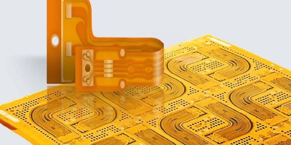
A flex PCB is a PCB that utilizes flexible substrate materials, allowing the board to bend, twist, and flex without damage during use. The conductors and components themselves can also bend to conform to the dynamic shape of the flex PCB. This is in contrast to traditional rigid PCBs, which use completely rigid boards and are not designed to flex.
A flex PCB can bend and conform to a wide variety of shapes
Flex circuits have conductive pathways etched from copper sheets which are laminated onto a thin insulating flexible substrate, usually a polyimide film or polyester. The surface-mount electronic components are also attached to the substrate. The flexible substrate gives the PCB its ability to be manipulated into and hold dynamic three-dimensional shapes.
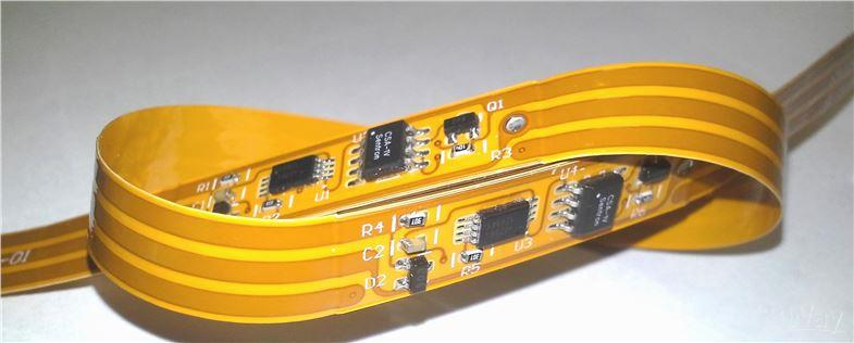
Connectors and components can be mounted on the flex circuit itself or integrated through stamped features like pockets or cutouts. Flex PCBs also often have rigid sections or segments to allow for component mounting and connection. Vias and other plated through holes (PTHs) can be implemented to allow circuit interconnections between layers for multilayer flex boards.
Benefits and Advantages of Flex PCBs
There are many notable benefits that make flex PCBs advantageous compared to rigid boards for certain applications:
Dynamic Movement and Shapes
The flexible and pliable nature of flex circuits allows them to be manipulated into shapes not possible with rigid boards. They can be bent and folded to fit into tight, constrained spaces in devices and products. Flex circuits are ideal for implementing connections and electronics that require dynamic movement or articulation.
Lightweight
Since only thin flexible substrate materials are used, flex PCBs are extremely lightweight compared to rigid boards using thick layers of FR-4 and glass fibers. This makes them well suited for lightweight, portable applications where minimal mass is desired.
Reliable Flexibility
While able to bend, twist, and conform to shapes, flex circuits are designed to withstand repeated dynamic flexing without damage. The conductors and materials used are durable enough to maintain the circuit integrity through extensive flexing motions.
Thin Profile
The thin flexible substrates used in flex PCBs allow them to hug tight contours and take up less space than thick rigid boards. This allows flex circuits to fit into very thin and compact product enclosures and packages.
Cost Effective
For short production runs, flex PCB fabrication can have a lower overall cost compared to rigid boards. This is because they require less layers and materials, and allow more simplified assembly processes in some cases.
Improved Aesthetics
The tight and dynamic fit, thin profile, and flexibility of flex circuits allows for improved aesthetics for consumer products compared to bulky rigid PCB implementations. The flex boards better conform to the industrial design requirements of modern devices.
Enhanced Reliability
With no solder joints to crack or break as a board bends, and durable flexible materials, flex PCBs enhance reliability in dynamic applications compared to alternatives. They are engineered to withstand repeated flexing without failure for long service life.
In summary, for any application where size, weight, complexity, reliability with motion, or aesthetics are priorities, flex PCBs should be strongly considered over rigid boards. Next we’ll look at some of the most common applications taking advantage of flex circuits.
Common Applications and Uses
Some of the most popular applications and end uses of flex PCB technology include:
Consumer Electronics
- Laptops
- Mobile phones
- Digital cameras
- Wearables
- Game controllers
- Printers
For small form factor consumer electronics that require compact, lightweight PCBs that can bend and twist to fit inside the enclosure, flex circuits are the perfect solution. Mobile consumer tech pushes the cutting edge of product miniaturization, which flex PCBs are uniquely suited for.
Medical Devices
- Hearing aids
- Blood glucose monitors
- Ultrasound probes
- Catheters
In medical devices like hearing aids that require PCBs to fit into extremely tight spaces close to the human body, flex circuits allow for circuits to be folded and manipulated to properly fit. They are also used in invasive devices like endoscopes that must bend and flex to navigate within the human body.
Automotive Electronics
- Advanced driver assistance systems
- Transmission control units
- Engine control units
- Sensors
Flex PCBs are increasingly used in cars and vehicles where electronics must withstand vibration, shocks, and repeated movement without compromise. Flex circuits maintain signal integrity under rugged conditions.
Aerospace Applications
- Unmanned aerial vehicles (UAVs)
- Avionics equipment
- Radars
- Missile guidance systems
In aircraft, satellites, and other aerospace systems, size and weight constraints are extremely tight. Flex PCBs provide reliable connectivity while saving space and weight to meet the demands.
Military Systems
- Portable communications
- Wearable electronics
- Munitions guidance
The small, lightweight, and rugged characteristics of flex PCBs make them suitable for many mobile and high-shock military electronics applications. The Defense sector is a major adopter of flex circuit PCBs.
Consumer Appliances
- Microwaves
- Coffee makers
- Washing machines
For the embedded electronics and controls in home and kitchen appliances, flex PCBs can provide reliable performance and save space in the compact product enclosures.
Wearable Technology
- Smart watches
- Fitness trackers
- Smart glasses
To make comfortable wearable devices, PCBs must be lightweight, thin, and able to flex and bend with natural body movements. Flex circuits are ideal to integrate electronics into clothing and accessories.
As you can see, flex PCBs span an incredibly wide range of applications, from tiny hearing aids to large missiles and radar systems. Their unique characteristics make them the ideal solution where rigid PCBs fall short.
How Flex Circuits Are Manufactured
The specialized materials, processes, and equipment used to fabricate flex PCBs give them unique properties and capabilities that cannot be achieved with rigid circuit boards. Here is an overview of how flex circuits are typically manufactured:
Substrate Material Lamination
The flexible substrate “core” material, such as polyimide or polyester film, is provided on large rolls and sheets. Multiple layers of substrate are laminated together using adhesive and heat pressure rollers to form a multi-layer board. Rigid layers or segments can also be integrated using stiffeners.
Photolithography Patterning
A photoresist dry film is applied on the substrate, and then it is exposed to UV light through a photomask pattern. Photolithography techniques similar to rigid PCB fabrication are used to etch and define the copper conductor traces.
Plating and Coating
Additional metal plating and protective coatings are applied to the flex circuit to build up conductor thickness and provide environmental resistance. These include gold, nickel, solder mask, and other finishes.
Etching and Defining Conductors
The unexposed dry film is then chemically etched away, leaving only the desired copper conductor pattern on the substrate layer defined by photolithography. Repeat for each layer.
Component Assembly
SMT components are assembled onto the flex PCB using specialized flexible adhesives rather than solder. ICs can be directly wire bonded or flip chip mounted. Connectors are added.
Testing and Inspection
Each flex circuit board is electrically tested and parameters verified. Automated optical inspection and x-ray imaging ensure quality standards are met.
Singulation
Individual flex boards are mechanically cut or punched out from the larger substrate panels after fabrication is completed.
With these essential steps, flex PCB manufacturers can produce precision flex circuits to meet the demands of advanced flex board applications.
Design Considerations and Guidelines
When designing a flex PCB, engineers must consider several factors specific to flex circuits that may differ from rigid board design:
Layer Stacking and Stiffeners
Careful planning of the layer stackup is critical, including which areas should have rigid sections vs dynamic flex zones. Stiffeners and spacers are added selectively.
Conductor Layout
Traces must be routed linearly along the flexing axis as much as possible, and exiting corners avoided. Large copper fills should also be minimized.
Component Placement
Components are positioned selectively, keeping size and weights balanced. Larger parts are placed on rigid segments, while lighter devices can be on flexible sections.
Bend Radius
Minimum bend radius requirements based on materials must be met in flexing areas. Sharp folds that overstress conductors should be avoided.
Vias and Holes
Via construction differs, with filled laser-drilled microvias common. Plated through holes (PTH) require specialized drilling and are not always used.
Connectors and I/Os
Mating connections to off-board systems may need specialized flex-capable connectors. It helps to minimize connector locations.
Thermal Management
Careful analysis of heat dissipation across both rigid and flexible zones, and the selection of thermally conductive materials, is key.
With rigorous design practices, flex PCBs can be implemented into extremely compact, lightweight, and complex packages that meet the toughest mechanical, electrical, and thermal constraints.
The Future of Flex Circuit PCB Technology
Flex PCBs have already revolutionized the possibilities for electronic product design across numerous industries. As demand for smaller, lighter, more powerful, and more reliable electronics continues, flex circuits will take on an increasingly crucial role in enabling those advancement through their unique benefits. Here are some key trends to look out for:
- Continued miniaturization and higher densities. Flex PCBs will allow manufacturers to cram more computing power and functionality into impossibly small product form factors.
- More reliable flexible electronics. Flex circuit materials and conductor/substrate integration will improve, enabling flexible PCBs to reliably withstand even more exaggerated and repeated bending motions.
- Growing applications in medical technology. The biocompatibility and small size of flex circuits makes them ideally suited for medical devices and implants.
- Flexible printed electronics integration. As printed electronics on flex circuits mature, they will allow flexible PCBs to add touch, lighting, and display capabilities.
- Higher performance computing uses. Rigid-flex combos will provide interconnect solutions for things like high speed servers and data centers.
- Development of design tools and workflows optimized specifically for flexible PCBs rather than just adopted from rigid PCB tools.
- Additional industry standards around testing and materials for flex circuits, which currently lag behind standards for more mature rigid PCB technology.
With so many exciting possibilities on the horizon, it is certainly an interesting time to be designing flex PCBs! Electronic product developers now have an entirely new realm of options at their fingertips thanks to flex circuit technology. The benefits and applications of flex PCBs will only continue to expand.
Flex Circuit PCB FQA
What is the typical thickness of flex PCB substrates?
Flex PCB substrates are usually between 25-100 microns thick. Rigid sections can be up to 1000 microns thick. The thin flexible material allows an overall thin profile.
Can flex PCBs be manufactured in high volume?
Yes, flex PCB fabrication methods scale to high volume production. Reel-to-reel processes allow high throughput manufacturing.
Do flex circuits require special assembly equipment?
Specialized flex PCB assembly equipment is often needed. SMT pick-and-place, adhesive dispensing, and automated optical inspection tools designed for flex boards ensures quality and precision.
What are some limitations of flex PCB technology?
Limitations include max number of layers (usually 4-8), constraints around rigid sections, smaller component sizes, lower component densities, and more limited thermal management capabilities.
How long have flex PCBs been around?
The first flexible printed circuits were developed in the 1950s for military systems. Commercial applications grew in the following decades. Recent years have seen a surge of flex PCB implementations.
Conclusion
Flex circuit PCB technology represents an exciting shift in electronics design, enabling lighter, thinner, more reliable, and more visually appealing product implementations. With the rapid growth in cutting-edge consumer tech and devices, flex PCBs have become a crucial solution for packing ever more computing power and functionality into amazingly compact and sleek packages.
Engineers now have greatly expanded possibilities at their fingertips thanks to the unique capabilities of flex circuits. However, specialized design considerations must be made. With smart flex PCB design taking into account the mechanical, electrical, and thermal demands, flex circuits will continue to be a key technology moving forward as electronics become further integrated into our everyday lives.